A onetime investment in one of our shaper cutter heads will enable you to always get the exact profile that you need because these heads accept corrugated knives with a thickness of 14 or 516 of an inch that we custom produce for you or simply choose from our extensive selection of standard knives. Shaper tool headrar.

Solidworks Shaper Tool Head Part Assembly Youtube
Tool on a shaper can be set to cut horizontally on an angle or vertically.
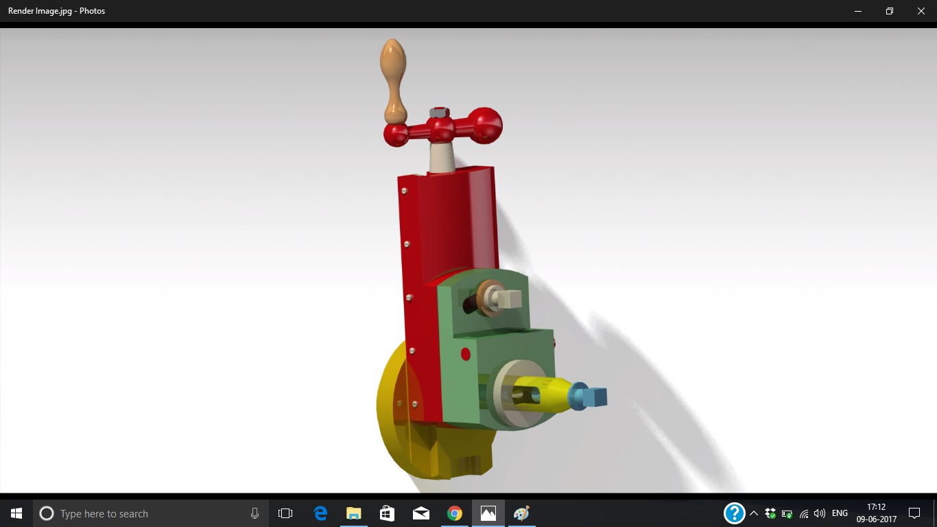
. After creating the assembly generate the top front right-side and the isometric view of the assembly. Shaper Tool Head Assembly Figure 1 The Shaper Tool Head assembly Figure 2 The exploded view of the Shaper Tool Head assembly. This video make by Vishwakarma Engineering Drawing Classes Bhilai Nagar.
SOLIDWORKS 2014 Other Rendering October 1st 2015 tool head of a shaper. Hello readers in todays article we will learn how a shaper machine works also we learn about the parts types operations specifications advantages disadvantages and applications of a shaper machine. Iterate edit and manufacture your concepts seamlessly on an award-winning app.
So lets start with the definition of a shaper machine. Load in 3D viewer Uploaded by Anonymous. The tool head slides in a dovetail at the front of the ram utilizing T-bolt sand is fastened to the ram on a circular plate so that it can be rotated for making angular cuts.
Shaper Machine is a production machine in which the single point cutting tools are attached and the workpiece is fixed and while moving forward the tool cuts the workpiece and in return there is no cut on the workpiece and used for producing flat and angular surfaces. Up to 24 cash back Machine Construction MD 121 Drawing Sheet 8. 16 Nov 2012 256 PM crystal.
The dimensions of the components are given in Figures 3 through 7. A 14 shaper can machine a cube 14 x 14 x 14. It is a sub-assembly of the tool head of a shaping machine.
Its cut is analogous to that of a lathe except that it is archetypally linear instead of helical. A shaper is a machine tool that uses reciprocating straight line motion of the tool and a perpendicular feed of the job or the tool. Create and assemble all the components of the Tool Head of Shaping Machine shown in Figure 1 and Figure 2.
Commonly used types of shaper machines. The dimensions of the individual components are shown in Figures 3 through 20. You can include balloons in your drawing views to identify specific parts and then add a parts.
CATIA V5 Rendering March 24th 2014 shaper tool head assembly. Shaper Tool Head Assembly. It is the device which holds the tool.
Shaper Tool Head Assembly 1 Create the Shaper Tool Head assembly as shown in Figure 1. Model Link Given Below Link. It is used for holding the shaper cutting tool.
Published 6 years ago in 3D Modeling Design. The design of the clapper block is such that it relieves the tool during the return stroke. A shaper is a machine tool which holds and locates a workpiece on a table and machines or cuts the workpiece by feeding it against a reciprocating cutting tool.
In other words the ram of the shaper moves a single point cutting tool back-and-forth and on each forward stroke the tool removes a chip of metal from the workpiece. Crank shapers gear. The ideas for the toolholder and arbor came from drawings made by Art Volz that are posted at the Yahoo Metal_Shapers groupThe drawings are in the Files section membership required as holder1jpg and holder2jpg and also available here.
It can swivel from 0 to 90 in a vertical plane. A 300 mm shaper can machine a cube 300 mm x 300 mm x 300 mm and so forth. A simple tool head assembly for Shaper Machine.
42 Draw cut Shaper Machine In these types of shaper machines the metal is removed in the backward motion of the ram. The Shaper Machine is a reciprocating type of machine tool basically used to produce Horizontal. Add the parts list similar to the one shown in Figure 3.
The following figure shows the details of a clapper block. Visualize 3D concepts for. Please let me know.
Shaper 8302 views - Mechanical Engineering A shaper is a type of machine tool that uses linear relative motion between the workpiece and a single-point cutting tool to machine a linear toolpath. This content and associated text is in no way sponsored by or affiliated with any company organization or real-world good that it may purport to portray. Back to model page.
443 views 0 comments 0 reviews Love22S. Shaper tool head assembly. This video explains about Tool head shaper Assembly Drawing Animation Assembly drawingHope you like this video Please Subscribe my channel for more video l.
The CAD files and renderings posted to this website are created uploaded and managed by third-party community members. August 29th 2012 Shaper Tool Fixing ScrewSLDPRT. In this shaper the tool is fixed in the tool head in the reverse direction so that it provides the cutting action in the reverse stroke of the ram.
Shapr3D combines the power of SOLIDWORKS and an award-winning UI. Model Link Given Below Link. A toolholder with an internal cutting arbor and a stubby toolpost.
August 29th 2012 Shaper tool head IGESIGS. After creating the assembly create its exploded view as shown in Figure 2. Shaper tool head assembly.
Project 3 Assembly Drawings ME 24-688 Introduction to CADCAE Tools Page 1 of 66 Annotating Assembly Drawings Assembly drawings typically include annotations that identify and describe the components in the assembly. The Popular Woodworking Magazine has named Shaper Origin Workstation to its list of the best tools and products of 2020. Create and access manufacturable models offline anywhere.
Rendering cad pro-e 3d-modelling. The workpiece is held in the vise of the shaper or. This page shows some tooling that I made for my Atlas 7B shaper.
IWF Challengers Award - 2018 The distinction of the IWF Challengers Award is given to outstanding companies who develop innovative technology and. By moving the wo. STEP IGES Rendering January 30th 2015 Machine tool.
Main purpose of this is to hold the tool which will be used in shaping and provide adjustments to it. Shaper size is determined by the largest cube which can be machined on the shaper. A wood shaper is a similar woodworking tool typically with a powered rotating cutting.
Types of Shapers There are three types of shapers. The tool head can be raised or lowered by hand feed for vertical cuts on the workpiece by its hand crank for precise depth. Great part files though.
How can I get an assembly drawing to see how the componets are assemblied and mated.

Shaper
Shaper Tool Head Assembly 3dexperience Edu

Shaper Tool Head Assembly 3d Cad Model Library Grabcad

Assembly Drawing Of Shaper Tool Head Slide Youtube
2

Shaper Tool Head Assembly Pdf Industrial Processes Metalworking

Tool Head Of A Shaper 3d Cad Model Library Grabcad
2
0 comments
Post a Comment